
Mobile: 19875181874
Tel: 020-81376938
Fax: 020-81376938
Email: sales@rogerwell.com
Address:The fourth floor of Block B, Wuyanqiao Industrial Village, No. 388 Fangxing Road, Liwan District, Guangzhou
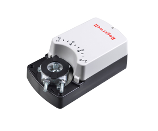
PCV-10A/AF PCV-15A/AF PCV-20A/AF PCV-30A/AF | Adjustable Air Valve actuator 10Nm/15Nm/20Nm/30Nm 0(2)-10V 0(4)-20mA Analog control |
Used to drive the HVAC and all kinds of mechanical ventilation system air valve Output Torque:10Nm,15Nm,20Nm,30Nm Supply Voltage:AC/DC 24V Control Mode: 0(2)-10v Analog Control 0(4)-20Ma analog control Feed Back: 0(2)-10v Analog 0(4)-20Ma analog -AF type with two sets of auxiliary switches | |
Technical parameter
PCV-10A/AF | PCV-15A/AF | PCV-15A/AF | PCV-30A/AF | ||
Electrical parameter | rated voltage | AC24V 50/60Hz DC24V | |||
Rated voltage range | AC/DC 19.2...28.8V | ||||
Power consumption | Running State 4.5W,standby state 0.5W | ||||
Wire Specification | 0.5mm² | ||||
Terminal Specification | Max 2.0mm² | ||||
Functional parameter | Torque | 10Nm | 15Nm | 20Nm | 30Nm |
Fit Air Valve area | 1.5m² | 3m² | 4m² | 5m² | |
Direction of rotation | Can Be selected by dial switch | ||||
Manual operation | Max 95° | ||||
Angle of rotation | Max 95° | ||||
Running time | 30S~45S(95°) | 30S~55S(95°) | 120S~160S(95°) | 120S~160S(95°) | |
Noise level | 45dB | ||||
Position Indication | Mechanical indication | ||||
Working Environment | Electrical Grade | III(Safe Low) | |||
Protection level | IP54 | ||||
Working Environment | -20…+50℃ | ||||
Storage ambient | -30…+80℃ | ||||
Storage ambient | 95%RH,No Dew | ||||
Size/weight | Dimensions | See size chart for details | |||
Length of air valve shaft | >50mm | ||||
Air Valve shaft | 10...20mm Circular Shaft 10X10...16X16 Square axis | ||||
Weight | 1.2-1.3 Kg | ||||
Wiring Diagram
Actuator wiring diagram

Auxiliary Switch Wiring Diagram
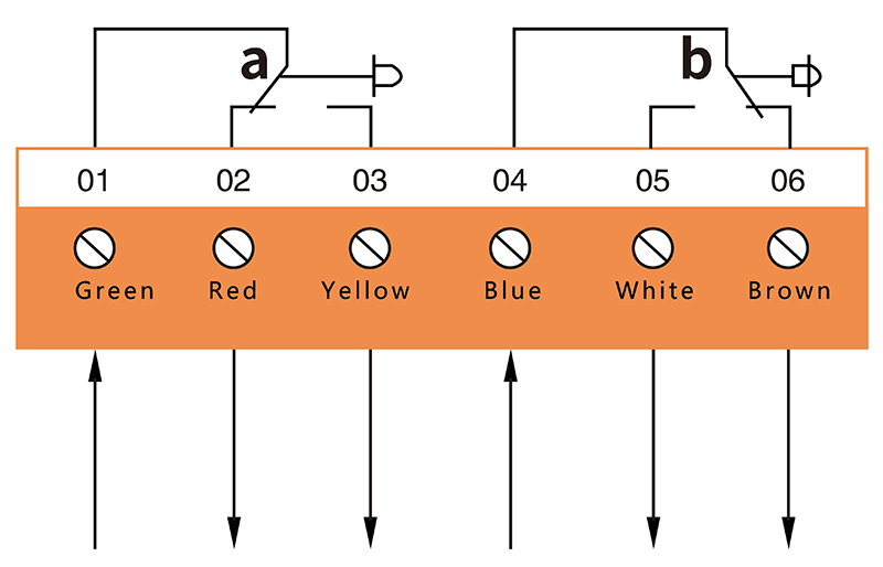
Resistive load 3A,220V
Perceptual load 1.5A,220V
Dimensional drawing(mm)

Dial switch setting
The first bit setting of the dial switch (setting the feedback signal mode) | The second bit of the dial switch is set (setting the starting point of the input signal) | The third bit setting of the dial switch (sets the input signal mode) | The third bit setting of the dial switch (sets the input signal mode) | The third bit setting of the dial switch (sets the input signal mode) |
 | 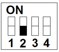 |  |  |  |
OFF Location: Voltage Signal 0(2) ... 10V feedback | OFF Location: Voltage 0... 10 V or current 0. . 20 Ma Input | OFF Location: Voltage 0... 10 V or current 0. . 20 Ma Input | OFF Position, the actuator rotates counterclockwise as the signal increases | Input Signal: 0... 10V Feedback Signal: 0... 10V actuator rotates clockwise as the signal increases |
 |  |  |  | |
ON Location: Current Signal (0(4) ... 20mA feedback | ON Location: Voltage 2... 10 V or current 4. . 20 Ma Input | ON Location: Current Signal 0(4) ... 20mA input | ON position, the actuator rotates clockwise as the signal increases |
-AF type auxiliary switch adjustment
Factory setting
Switch a | Terminal 01,02 | Terminal 01,03 |
0-10° | Open circuit | Short circuit |
10-90° | Short circuit | Open circuit |
Switch b | Terminal 04,05 | Terminal 04,06 |
0-80° | Open circuit | Short circuit |
80-90° | Short circuit | Open circuit |

Fixed auxiliary switch a: Turn The actuator clockwise to the angle to be set, loosen the screw of knob A, turn Knob a clockwise to just press down the micro switch, maintain this position, re-tighten the screw.
Set Auxiliary switch b: Turn The actuator clockwise to the angle to be set, loosen the screw of Knob B, Turn Knob B clockwise to release the micro switch just right, keep this position, re-tighten the screw.
Points to note
1.This valve actuator shall not be used outside the specified application, especially not on aircraft.
2.Non-professional installation personnel do not open the actuator Shell, strictly prohibited live wiring.
3.This Air Valve actuator contains electronic component and shall not be treated as ordinary household waste and shall be treated in accordance with local laws and regulations.